Baseline demographic and clinical characteristics
In the following section each case will be discussed separately. A summary of the five cases is depicted in [Table 1].
Case 1 : A 70-year-old man suffering from ischemic VTs with recurrent ICD shocks despite use of amiodarone, underwent 3 endocardial VT ablations. Using an activation map, an isthmus was located and targeted in the middle of the inferoposterior to septal area of the left ventricle (LV) (areas 3/4/5/6 according to Josephson[12,13], [Figure 2]). Substrate modification of the inferior LV was performed during the second ablation. Since this neither provided long-term freedom of VT, and because of suspicion for an epicardial origin on ECG (wide QRS, pseudo delta wave, [Figure 3A]), a percutaneous epicardial ablation was proposed. Access to the pericardium with a subxiphoideal puncture failed (dry tap), and per hospital protocol surgical access is not performed in the electrophysiology (EP) lab. Therefore, only an endocardial ablation was conducted. The exits of 2 induced VTs were mapped at areas 7 to 10 (apical low lateral/ inferoposterolateral/anterolateral/lateral basal), where several RF applications were performed. Another VT led to supplemental RF applications at areas 5/6/7 (inferior/inferoposterior/apical low lateral).
In the next days the patient again suffered from sustained VTs and therefore underwent a hybrid VT ablation in the OR, during which an endo- and epicardial ventricular substrate modification (LAVA) was performed (Fig.3B-C-D). A total of 55 applications were performed endocardially in area 5/6/7 (inferior/inferoposterior/apical low lateral), and 19 epicardially. The duration of each application was 30 seconds, the average power 36W and the maximum power 41W. No VT could be induced at the end. The patient was discharged after 3 days in the intensive care unit and 4 days on the regular ward.
After the hybrid procedure the incidence of VT while on beta-blockade was significantly reduced to sporadic sustained VT less than once per year. Twenty-one months after the ablation a sustained VT recurred (RBBB, undefined axis, R/S transition V4, CL440ms), leading to repeat endocardial ablation inferior/lateral (areas 5 to 10). In the following 18 months the patient did not suffer recurrences.
Figure 2 Endocardial Areas of Josephson[13]
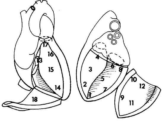
Left ventricle: 1 = apex, 2 = apical septum, 3 = mid septum, 4 = basal septum, 5 = inferior, 6 = inferoposterior, 7 = apical low lateral, 8 = inferoposterolateral, 9 = anterolateral, 10 = lateral basal, 11 = midanterior, 12 = superior basal. Right ventricle: 13 = tricuspid annulus/basal septum, 14 = apex, 15 = mid septum, 16 = anterior septum, 17 = outflow tract, 18 = lateral/free wall.
Figure 3 Electrocardiogram and electro-anatomical maps of case 1
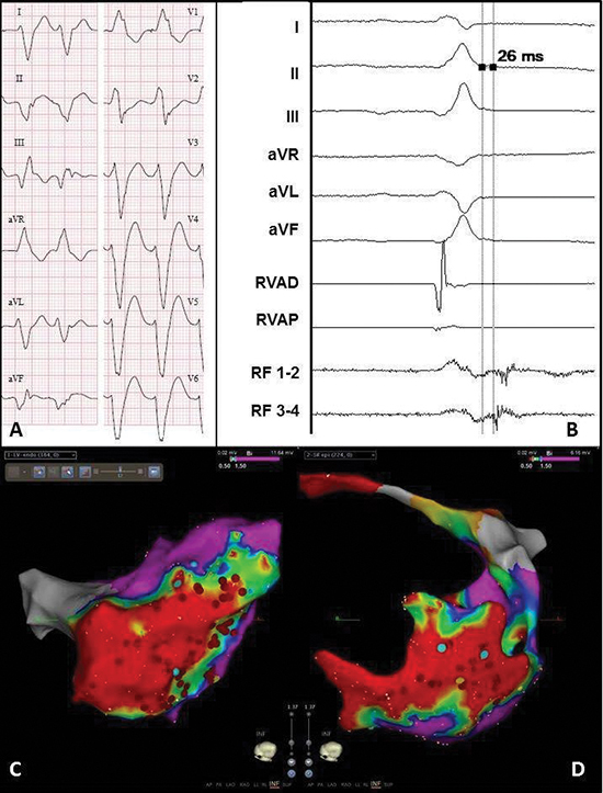
A. Twelve-lead electrocardiogram showing a ventricular tachycardia (115bpm) with right bundle branch block morphology, right axis and early R-wave transition, suggesting a lateral mid-apical origin in the left ventricle. Pseudo delta wave and wide QRS suggest epicardial origin.
B. Recording obtained in sinus rhythm during the procedure showing local abnormal ventricular activation at the RF catheter. RVAD/P = right ventricular apex distal/proximal, RF = radiofrequency.
C. Inferior view of the bipolar endocardial voltage map showing a low voltage area from inferoposterior to low apical in the lateral wall (area 5/6/7). Red dots = RF applications.
D. Inferior view of the bipolar epicardial voltage map showing a low voltage area consistent with the endocardial
map. Red dots = RF applications.
Case 2 : An 80-year-old male with a history of MI and bilateral pulmonary vein isolation for paroxysmal AF, presented with a sustained VT two years after cardiac surgery. Despite amiodarone, recurrences with a ventricular rate below the detection zone of the ICD recurred. The LV voltage map during the first endocardial VT ablation showed a low voltage area from area 5/6 (inferior/inferoposterior) to 7/8 (apical low lateral/inferoposterolateral), and an early activation at area 7 (apical low lateral). RF applications in that area terminated the VT. Substrate modification in the exit zone of the VT was also performed (ablation line around the border zone and additional applications at areas 7/8, apical low lateral/inferoposterolateral). Ten days later the same VT recurred, followed by endocardial substrate modification in area 9 (anterolateral).
One month later a hybrid VT ablation was performed for recurrences despite the use of amiodarone and metoprolol ([Figure 4A]). Endocardially, the exit site of the clinical VT was mapped at area 8 (inferoposterolateral). A second VT with a more septal exit could be induced as well. The exit zones and late potentials [Figure 4B] were ablated (14 applications, mean 70 seconds, average output 39W). Adhesions and grafts of the previous cardiac operation, hindered the procedure, but safe mapping and ablation could be performed. The epicardial voltage map correlated with the endocardial map [Figure 4C-Figure 4D]. The exit was also mapped at area 8 (inferoposterolateral), and this zone and late potentials were ablated epicardially (11 applications, mean 45 seconds, average output 34W). Because of transient ST-segment elevations inferior, no more VT induction or ablation was performed. After 2 days in the intensive care unit, and 2 days on the regular ward, the patient was discharged.
During 12 months follow-up the patient did not suffer from any recurrences, while using metoprolol 50mg and amiodarone 100mg once per day.
Figure 4 Electrocardiogram and electro-anatomical maps of case 2
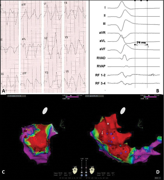
A. Twelve-lead electrocardiogram showing a ventricular tachycardia (150bpm) with right bundle branch block morphology, right axis and normal R-wave transition suggesting a lateral-basal origin in the left ventricle.
Pseudo delta wave and wide QRS suggest epicardial origin.
B. Recording obtained in sinus rhythm during the procedure showing local abnormal ventricular activation. RVAD/P = right ventricular apex distal/proximal, RF = radiofrequency.
C. Inferior view of the bipolar endocardial voltage map showing low voltages inferior/inferoposterior (area 5/6). Red dots = RF applications, purple dots = late potentials.
D. RAO view of the bipolar epicardial voltage map showing low voltage area practically consistent with the endocardial map, though more extensive at the lateral wall (area 7/8). Red dots = RF applications, purple dots = late potentials.
Case 3 : A 56-year-old man was admitted with a therapy refractory incessant VT. On echocardiogram LV function was decreased to 30%, and the right ventricle (RV) was minimally dilated with also decreased function. ARVC was not seen on magnetic resonance imaging (MRI), but 2 of the major ARVC criteria were present: biopsy showed minimal fibrosis and myocytes with vacuolisation, and ECG showed sustained VTs of LBBB morphology with superior axis and inverted T waves in the right precordial leads in SR. Due to hemodynamic instability the patient was connected to extracorporeal life support. An endocardial electro-anatomical map of the RV (Ensite NaVX, St. Jude Medical) showed focal activation (i.e. earliest activation time -20mS during VT) at areas 15 (mid-septum) and 18 (lateral), and RF applications at and between those areas terminated the VT.
When trying to reduce the flow of the external support in the next days, VTs of morphology 1 and 2 recurred. These could not be induced during the second and third endocardial ablation, and a RV bipolar voltage map (Carto, Biosense Webster) showed no zones of low voltages. However, using unipolar signals an extensive low voltage zone (<5.5mV [14]) at areas 17 (outflow tract) and 18 (lateral) was seen. Epicardial access failed because the injected contrast could not be seen in the epicardium. Therefore only endocardial ablation was performed at the lateral area 18 (48C, 40W). The last application resulted in a steam pop, substantial loss of blood via the inserted pigtail in the pericardium, and hemodynamic instability. A hole in the RV free wall was sutured via a sternotomy performed in the EP lab. One day after discontinuation of external support, a therapy refractory sustained VT recurred (morphology no. 3). Since the VT terminated on arrival in the EP lab and could not be induced, it was decided to perform a hybrid VT ablation via resternotomy in the OR. After administration of isoprenaline a sustained VT was induced [Figure 5A-Figure 5B]. The endocardial activation map showed prepotentials at areas 13, 14 and 18 (basal, apical and RV free wall, [Figure 5C]), but hereafter the VT stopped. The bipolar epicardial voltage map showed low voltages in basically all areas of the RV ([Figure 5D]). Since the RF catheter could not be stabilized well on the beating hart, it was changed for a cryo-pen (AtriCure, Ohio, USA). A lesion of 4x4cm was made (8 applications of 120ms) at area 18 (lateral). No additional endocardial ablation was performed because of the recent perforation. No VT could be induced at the end of the procedure. After 6 days in the intensive care unit, the patient was transferred to his own hospital. Before discharge an ICD was implanted.
During one-year follow-up the patient maintained SR using metoprolol 100mg once per day.
Figure 5 Electrocardiogram and electro-anatomical maps of case 3
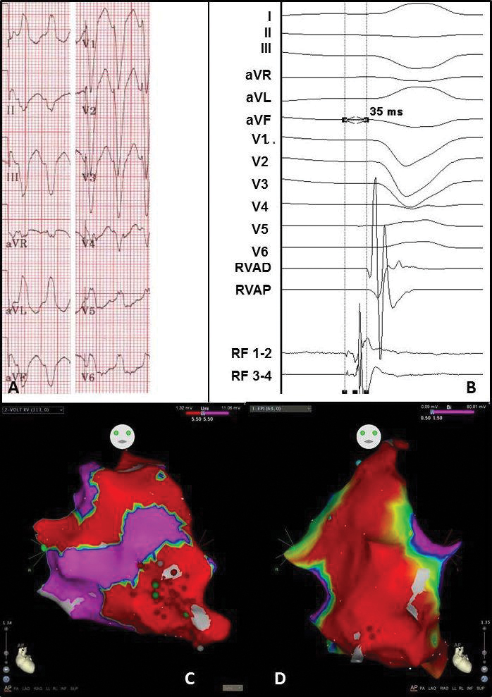
A. Twelve-lead electrocardiogram showing a ventricular tachycardia (180bpm) with left bundle branch block morphology and superior axis, suggesting origin in the right ventricle (RV) free wall.
B. Recording obtained in sinus rhythm during the procedure showing prepotentials. RVAD/P = right ventricular apex distal/proximal, RF = radiofrequency.
C. Anterior-posterior (AP) view of the unipolar endocardial voltage map showing a low voltage area at the apex and RV free wall (area 14 and 18). Red dots = RF applications
D. Anterior-posterior (AP) view of the bipolar epicardial voltage map showing a low voltage area at basically the total apex and RV free wall (area 14 and 18). Red dots = RF applications
Case 4 : A 67-year-old man, recently diagnosed with paroxysmal AF, was admitted to the hospital suffering a symptomatic monomorphic VT causing hemodynamic instability. Magnetic resonance imaging showed hypokinesia and subepicardial fibrosis of the basal inferolateral and inferior walls, and a normal RV [Figure 6]. DNA analysis showed a mutation in the PRKAG2 gene (c432dup mutation). Most probably this relates to a pathogenic mutation, however this mutation has not been described before nor is it known in genetic databases. A few months after ICD implantation, recurrent VTs (same morphology) occurred. Since there was clear evidence for an epicardial origin (imaging and ECG), it was decided to perform a left-sided thoracoscopic hybrid ablation. Macroscopically only minimal epicardial fibrosis was visible at area 8 and 10 (inferoposterolateral and lateral basal). The endocardial unipolar voltage map showed low voltages (<8.3mV, [15]) at those areas ([Figure 7C]), and the epicardial unipolar map also at the anterolateral area 9 ([Figure 7D]). No VT could be induced. Eight epicardial RF applications were performed at areas 9/10 (anterolateral/lateral basal) with a mean of 35seconds per application (average output 30W). Due to the proximity of a coronary artery, area 8/9 (inferoposterolateral/anterolateral) could not be ablated epicardially and was only ablated endocardially (6 applications with a mean of 60seconds and an average output of 25W). Because of AF during the procedure, isolation of the right and left pulmonary veins in pairs (bipolar clamp, AtriCure) was performed via the left-sided thoracoscopy. No VT could be induced at the end of the procedure. After 1 days in the intensive care unit, and 6 days on the regular ward, the patient was discharged.
In the first three months after ablation two sustained VTs recurred (RBBB, inferior axis, absent R/S transition, CL 340 ms). Blood analysis showed that the amiodarone level was subtherapeutic, and for one week the dose was raised to 600mg daily. The following year he maintained SR.
Figure 6 Cardiac magnetic resonance image of case 4, short axis.
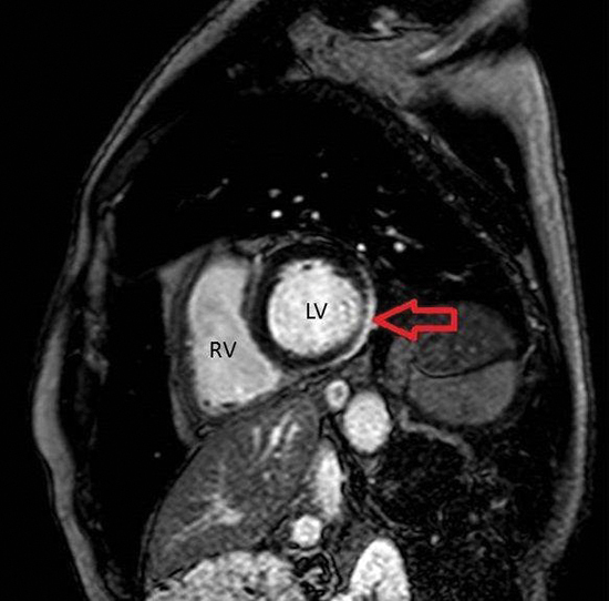
RV = Right Ventricle. LV = Left Ventricle. Red arrow: area of fibrosis (white).
Figure 7 Electrocardiogram and electro-anatomical maps of case 4
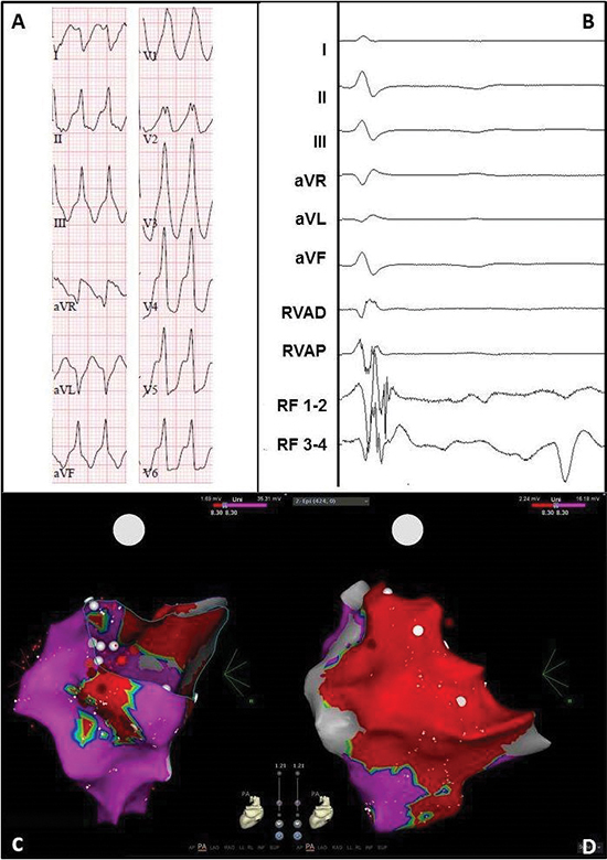
A. Twelve-lead electrocardiogram showing a ventricular tachycardia (206bpm) with right bundle branch block morphology, right inferior axis, and positive QRSs in all precordial leads, suggesting origin in the basal lateral wall of the left ventricle. Pseudo delta wave and wide QRS suggest epicardial origin.
B. Epicardial recording obtained in sinus rhythm during the procedure showing local abnormal ventricular activation. RVAD/P = right ventricular apex distal/proximal, RF = radiofrequency.
C. Posterior-anterior (PA) view of the unipolar endocardial voltage map showing a low voltage area inferoposterolateral and lateral basal (area 8/10). Red dots = RF applications.
D. PA view of the unipolar epicardial voltage map showing more extensive low voltages at the lateral basal area 10. Red dots = RF applications.
Case 5 : An 18-year-old male with working diagnosis ARVC (pre-syncopes, minimal dilated RV and frequent premature ventricular complexes (PVCs)), had recurrent ICD shocks and showed many non-sustained VTs. Despite the patient was suspected for being noncompliant to antiarrhythmic therapy and for excessive use of cannabis and alcohol, an endocardial VT ablation was performed. The bipolar voltage map showed low voltages at the basal septum, outflow tract and basal inferior RV (areas 13/17/18), wherefore ventricular substrate modification. No VT could be induced afterwards. In the following period the amount of runs of PVCs, non-sustained VTs and VTs increased ([Figure 8A-Figure 8B]), and a hybrid VT ablation via right-sided thoracoscopy was performed. No VT could be induced, but the bipolar endocardial voltage map showed low voltages at areas 13/15-18 (basal septum/mid septum/anterior septum/outflow tract/basal inferior,[Figure 8C]). The bipolar epicardial voltage map showed low voltage zones and LAVA at area 13 (basal septum), and low voltages at area 17 (outflow tract, Fig 8D). The unipolar endocardial map showed low voltages (<8.0mV) involving almost all areas. A first PVC was endocardially mapped and epicardialy and endocardially ablated at area 18 using RF (7 applications with a mean of 51 seconds per application, an average power of 34W and maximum power of 38W). A second PVC could be mapped epicardially at area 17, and was ablated epicardially using RF (5 applications with a mean of 53 seconds, average power of 71W and maximum power of 75W). No VT could be induced at the end of the procedure. After 3 days on the regular ward the patient was discharged.
During 12 months follow-up SR was maintained using sotalol 40mg twice per day.
Figure 8 Electrocardiogram and electro-anatomical maps of case 5
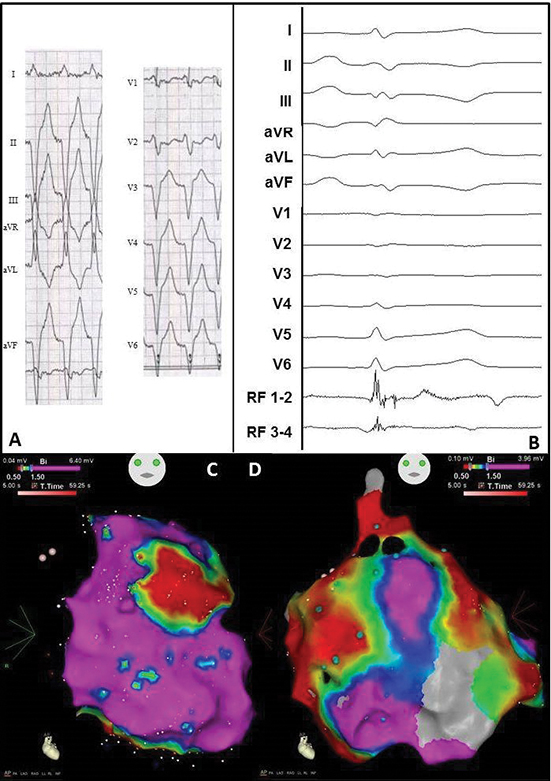
A. Twelve-lead electrocardiogram showing a ventricular tachycardia (110bpm) with left bundle branch morphology, superior axis and R/S transition in V3, suggesting origin in mid RV. No specific signs for epicardial origin.
B. Epicardial recording obtained in sinus rhythm during the procedure showing local abnormal ventricular activation. RVAD/P = right ventricular apex distal/proximal, RF = radiofrequency.
C. Anterior-posterior (AP) view of the bipolar endocardial voltage map showing a low voltage area from the basal inferior RV to mid inferior RV and RV outflow tract (areas 13/15-18). Red dots = RF applications.
D. AP view of the bipolar epicardial voltage map showing a more extensive low voltage area consistent with the endocardial map. Red dots = RF applications.
Table 1. Patient and procedural characteristics
|
Pre-operative |
Operative |
Post-operative |
| Case |
Gender |
Age |
VT Etiology |
Location |
EF (%) |
First VT |
Other VT |
AAD |
ICD |
CA |
Access |
Scar |
FU |
| 1 |
M |
70 |
Ischemic |
RCA, LCX, LMA |
37 |
LBBB, superior axis, R/S V2, CL 320ms |
2/3. RBBB, inferior axis, CL 310-360ms,
4. LBBB superior axis, R/S V6, CL 390ms,
5. LBBB, superior axis, R/S V2, CL 530ms
|
Amiodarone |
+ |
3 |
Left Lateral |
AL/I |
1 CA, AAD- |
| 2 |
M |
80 |
Ischemic |
LAD, LMA, RDP |
41 |
RBBB, inferior axis, R/S V4, CL 400ms |
2. superior axis, CL 395ms, rest unknown |
Amiodarone |
+ |
2 |
Left Lateral |
IL |
SR, AAD+ |
| 3 |
M |
56 |
ARVC |
N.A. |
35 |
LBBB, superior axis, R/S V5, CL 560ms |
2. LBBB, superior axis R/S V4, CL 440ms
3.LBBB, inferior axis, R-S V4, CL 420ms
|
None |
- |
3 |
Sternotomy |
N.A. |
SR, AAD- |
| 4 |
M |
68 |
Unknown |
N.A. |
57 |
RBBB, inferior axis, R/S V5, CL 230ms |
- |
None |
+ |
0 |
Left thoracoscopy |
N.A. |
VT, AAD+ |
| 5 |
M |
35 |
ARVC |
N.A. |
57 |
LBBB, inferior axis, R/S V3, CL 380ms |
2. PVC: LBBB, superior axis, R/S V5-6
3. PVC: LBBB, inferior axis, R/S V5-6
|
Sotalol |
+ |
1 |
Right thoracoscopy |
N.A. |
SR, AAD+ |
EF = ejection fraction, VT = ventricular tachycardia, AAD = antiarrhythmic drug, ICD= implantable cardioverter-defibrillator, CA = catheter ablation, FU = follow-up, M = male, ARVC = arrhythmogenic right ventricular cardiomyopathy, RCA = right coronary artery, LCX = left circumflex artery, LMA = left marginal artery, LAD = left anterior descending artery, RPD = right posterior descending artery, N.A. = not applicable, LBBB = left bundle branch block, RBBB = right bundle branch block, R/S = r-wave/s-wave transition, CL = cycle length, AL = anterolateral, I = inferior, IL = inferolateral, SR = sinus rhythm