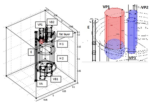
Let us introduce the model geometrical setting. Critical geometrical parameters affecting the thermal field during CA are the esophagus thickness, its distance from the left atrium, and the epicardial fat layer (EFL) thickness. These parameters may vary considerably. Therefore, a mathematical model can only refer to an average situation. Of course, the model can be adapted to specific cases when information on the actual location of the relevant organs is available.
Nevertheless, since the thermal diffusivity of the involved tissues is within a rather narrow range, even computing the thermal field for a standard case may give a significant hint of what we can expect when e.g. the esophagus happens to be closer to the heart.
Since we are facing a great anatomical diversity, it makes sense to select a simplified geometry (a strategy also adopted by Berjano [25], Berjano and Hornero [26]), capturing the thermal field in the region of interest with reasonable approximation. The esophagus is represented by a straight cylinder E, whose lumen is in close contact to the probe, in consideration of the fact that it presents a constriction in correspondence of the LA (nice pictures can be found at https://www.med-ed.virginia.edu/courses/rad/gi/esophagus/anat01.html).
The heart is an immobile cylinder H [Figure 1], surrounded by a fat layer and separated in two halves by a septum of negligible thickness parallel to the blood flow, impervious to blood and pervious to heat [Figure 1]. Heart pulsations can be averaged out during the time of one application (equivalent to two of three hundreds heartbeats) so that blood flow can be taken stationary. Each half of the cylinder H has two chambers H1 (atria) and H2 (ventricles) having different thickness. We further simplify geometry, with no substantial alteration of the thermal field, considering a scheme in which two PVs merge (namely those that are going to be occluded by the cryo-balloon). Thus, we sketch blood supply to the left atrium by means of three vessels: one large, VP1, two small, VP2, VP3. We put VP1 as close as possible to the cylinder E in order to maximize esophageal exposure to the cryo source. How to sketch blood outflow and inflow in other chambers is immaterial from the point of view of the thermal behavior, so in our geometrical scheme we put just one duct VA leaving the left ventricle and two (VB1, VB2) assuring blood flow through the right chambers. A flat velocity profile determined by the imposed discharge is assumed at each cross section to avoid the unnecessary complexity of fluid dynamics.
Figure 1. Sketch of the geometrical setting (left) and detail of the balloon region (right).

The idealized elements described so far are placed in a cubic box, whose side is 20 cm long. The initial temperature is assumed to be 37°C everywhere, as well as the temperature TB of the blood perfusing the organs.
Of course, this setting is quite sketchy, but it captures the basic elements, as far as thermal conduction is concerned.
We considered two sets of geometrical parameters representing non-exceptional anatomical structures, but combined in such a way to imply rather different thermal behaviors. Clearly, the presence of much thicker EFL, like in obese patients, would act as a very effective thermal shield for the esophagus. Among the papers consulted to choose the anatomical data, we quote Xia [28] and Bertaso [29],
SET 1 (largely safe conditions): esophagus thickness 3mm, EFL thickness 3mm, esophagus-balloon surface distance 1.10 cm;
SET 2 (border to critical): esophagus thickness 2.5mm, EFL thickness 1mm, esophagus-balloon surface distance 0.65cm.
Let us now sketch the equations governing heat transport. For the blood flowing through H, transport is due to diffusion and convection:
Equation 1

(see [Table 1] for density ρB, specific heat cB, and thermal conductivity kB ), where Δ is the Laplace operator and v is blood velocity, supposed uniform over cross sections). In the composite domain esophagus + connective + heart + EFL we use Pennes equation, also known as the bioheat equation
Equation 2

where ρ, c, k take the corresponding value listed in [Table 1] (from Berjano [25] and Berjano and Hornero [30]), TB is equal to 37°C, and ω(T) is the temperature dependent blood perfusion rate, given as
Equation 3

as long as it is positive, and zero otherwise, with w0 as in [Table 1] (from Holmes [31]).
Table 1. Tissues thermal properties
|
|
Ρ (Kg m–3)
|
c
(J kg–1 K–1)
|
k (W m–1 K–1)
|
Ω
0
(s
−
1
)
|
|
Esophagus
|
1000
|
3700
|
0.4
|
3×10⁻³
|
|
Connective
|
1000
|
3200
|
0.4
|
6×10⁻⁴
|
|
Fat
|
900
|
2200
|
0.2
|
5.5×10⁻⁴
|
|
Heart
|
1200
|
3200
|
0.7
|
0.017
|
|
VA. VB
|
1000
|
3200
|
0.4
|
-
|
|
Blood
|
1000
|
4180
|
0.54
|
-
|
There is no general agreement on the value to be given to the ratio w1/w0. Following Lakhssassi [32] we take w1/w0 =1.
In equation (2) we have neglected the source term expressing the metabolic heat production, estimated to be 1÷2 W/kg at rest.
In simulations we have used a 23mm diameter balloon at uniform temperature Tc = –70°C.
Two situations have been considered:
• 5 min cooling (a time never exceeded in the procedure)
• 4 min cooling, followed by the recovery of the baseline temperature in the balloon during the next 30 sec (this kind of simulation is important to understand how some of the relevant tissues keep cooling for a while after interruption of refrigerating gas).